Ecto Goggles ver7 Build Guide
This guide is a step-by-step walkthrough of the process I used to create my 7th version of Ecto Goggles and is an all-around path I take when making these props. If nothing else you may get some ideas for your own Ecto Goggles. If you have any questions or suggestion please email me:
Photos of the finished goggles can be found here: Ecto Goggles ver7
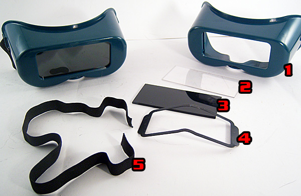
In the photo below, the pair of goggles I am starting with is on the left, while an exploded view of the parts is on the right. The frames (1) are a hard plastic so they will be durable and hold paint well compared to the soft vinyl most welding goggles are made from. The clear protective plate (2) we will save, however the dark glass (3) will be put in the scrap box for another project. Also saved are the view plate brace (4) and the elastic band (5):
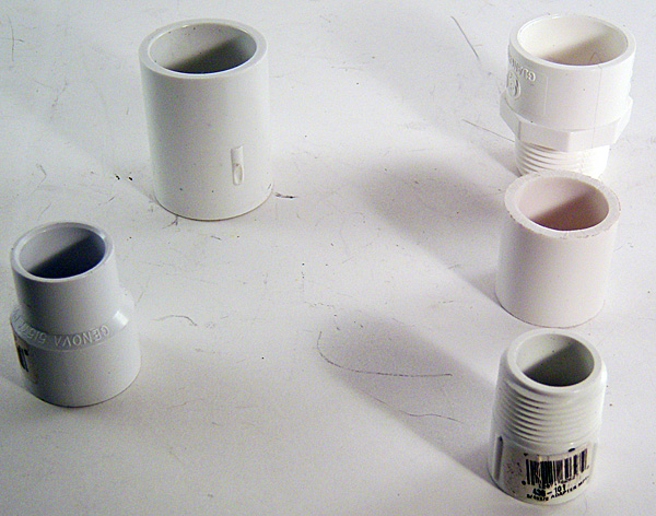
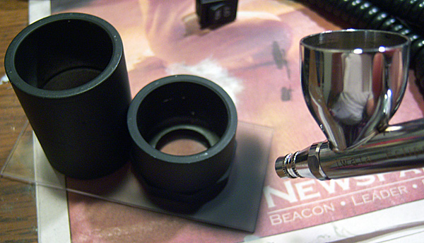
Now I choose some pieces of PVC to make up the two irregularly shaped lenses on the Ecto Goggles and lay the pieces out as they will go when fit together:
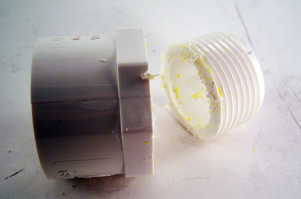
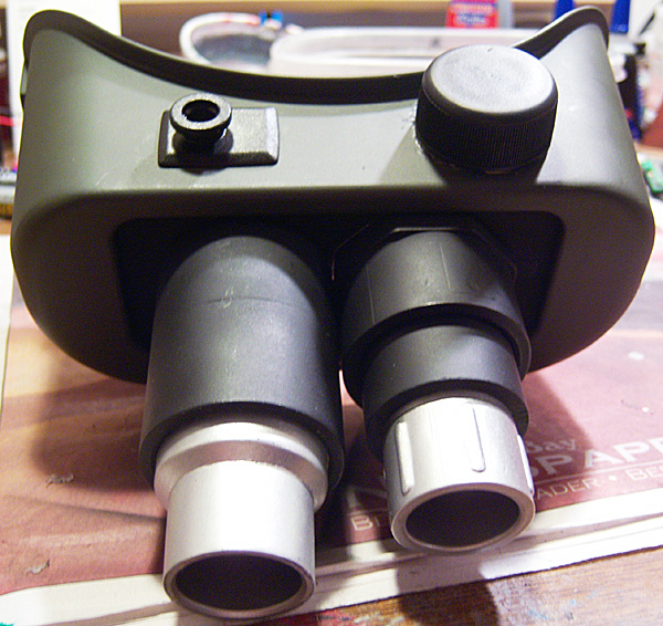
Here they are assembled. If you look at reference photos from Ghostbusters you'll notice the right lense is longer than the left, so here we need to cut off the threading from the left lense to shorten it:

Using a saw I remove the threading flush to the bottom of the PVC adaptor:

And I will also save this bit of threading, as I use it when creating the leg hosing for my Ghostbuster belt kits (throw nothing away!):
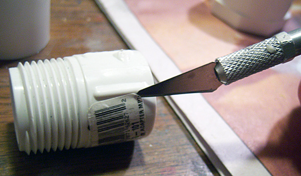
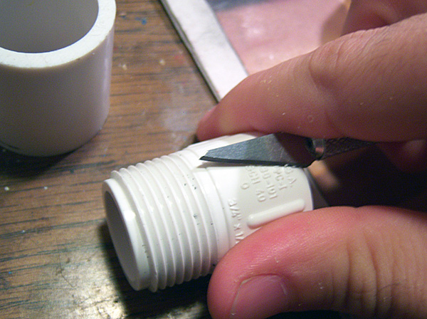
Most of the PVC pieces have bar code labels that need to be scraped off with an exacto:
And embossed lettering that I first whittle down with my blade:
Then remove what's left with a fine sanding disc on my dremel:

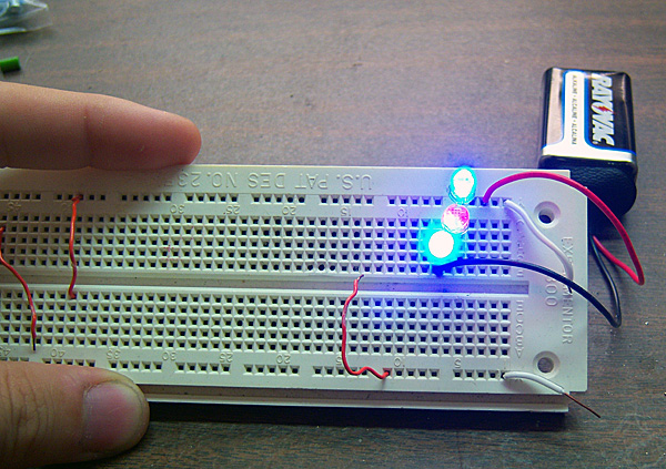
Now I determine what kind of lighting I want for this set of goggles. Here I test my circuit for 3 LEDs, each drawing 3 volts so they will run perfectly off of a 9 volt battery. The circuit will consist of 2 blue LEDs and 1 color strobing/flashing LED. The flashing LED will cause the regular blue LEDs to pulse and flash along with it for an interesting spector-scanning effect:
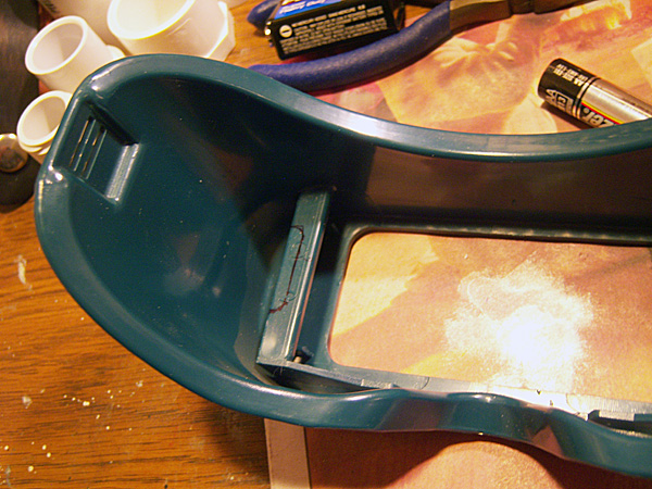
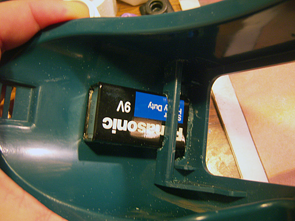
Now that I know what my power source is, I mark its placement on the goggle frames. In this case, I know I can cut a small groove for the battery just big enough to fit the battery and hold it in with tension. This eliminates the need to fabricate a battery holder and makes it easy for changing the battery in the future:

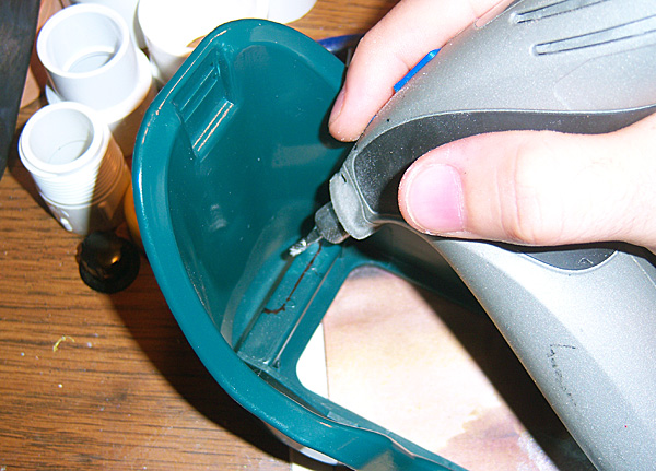
Now that I have my outline I can begin cutting out the groove:
It is important not to remove too much plastic so I cut slowly, stopping to test fit every few seconds:
Ah, perfect fit. I will clean up the flash created by the dremel but otherwise removing more plastic at this point would make the battery loose:
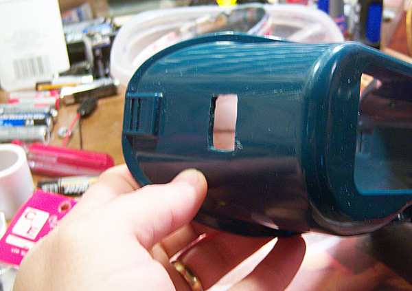
The same process is used to install the on/off switch. I choose to place it on the right hand side and draw its outline while I hold it in place:

The dremel creates a pretty nicely rectangular opening even with a rounded bit:
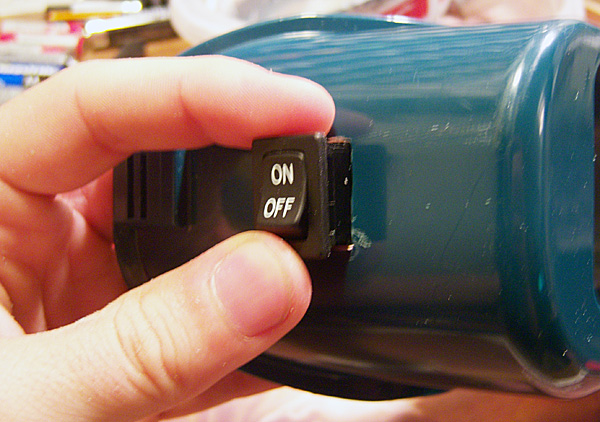
It does not have to be perfect as the switch has snaps on the top and bottom that will hold it in place when pushed into the opening. I test fit here to make sure it will go but not all the way as I don't want to install it before I solder my circuit later:
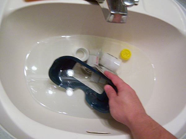
Now that all drilling and cutting is done it's time to prep the parts for painting. This involves wet sanding in warm water with 320 grit sand paper. I then rinse each part and leave it under a fan to completely dry it out:
Taking things outside I then base coat all parts in Krylon Flat Black:

Once the black dries I take Krylon Ultra Flat Olive Drab to the frames:

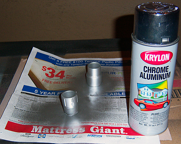
And for the ends of the lenses, Krylon Chrome Aluminum:
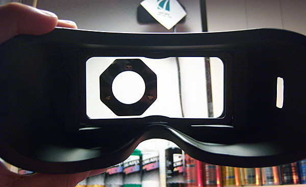
Once the paint has cured on the parts I reassemble the clear plate on the goggles and hold up each lense to determine its placement. I can rest the right lense on the work bench because it's longer, but the left lense has to be held up with my fingers. This means I will attach the left lense first:

Holding it in place, I carefully drill 3 small holes for the little brass screws:
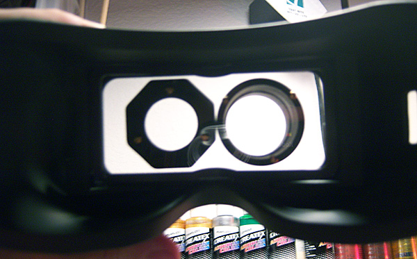
Now that I have my left lense on, I can put the right lense on the work bench and position it without having to hold it. Here are both lenses now screwed on:
Now I slide out the clear plate for painting. Both lenses must be screwed on tightly so no paint creeps under them or I won't be able to see out of the goggles later:
Using the airbrush with Tamiya Flat Black I paint the clear plate. The Tamiya blends nicely with the Krylon:
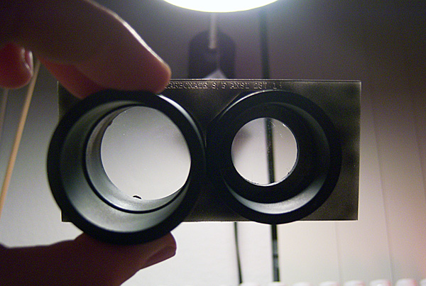
Now I have to hold up the clear plate to the light to see what areas need more black:
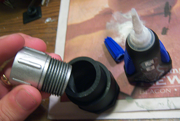
Now it's time to glue the lenses together. Because they now have paint it's a good idea to strip the bottom of the piece that will be fitting into the wider piece. This helps to ensure that when I push the two parts together that the silver paint doesn't start bunching up and coming out between where the two pieces meet. It's also good to score the areas that will be glued for a better bond:

Since the top of the left lense has threads I need not strip or score it, but apply the glue between the threading:
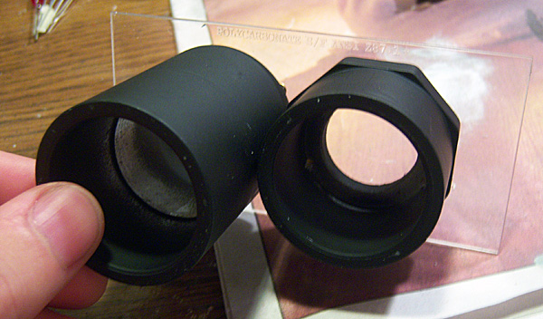
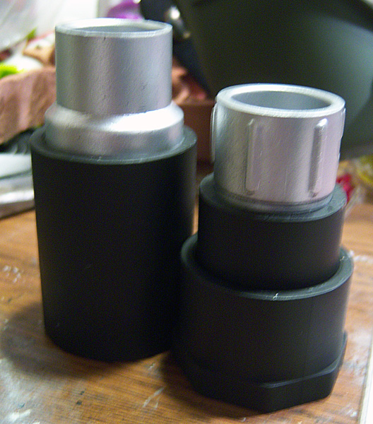
Here are the glued lenses. Time to check for any problems before proceeding:
Going back to the frames, I attach the clear plate with its metal brace and add some hot glue around it for extra hold and shock absorption:
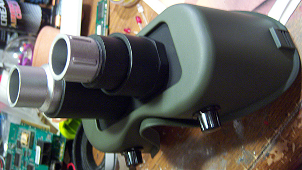
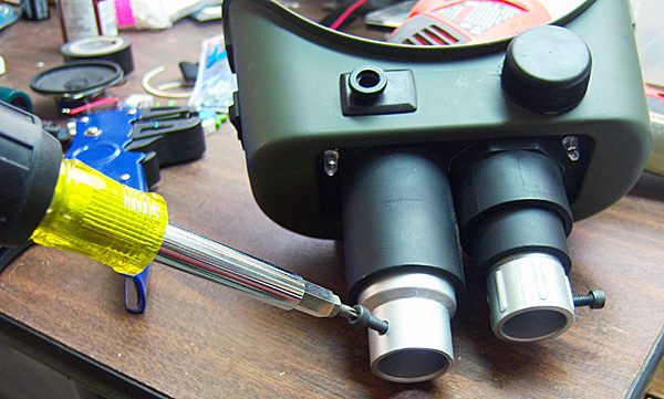
I now reattach the lenses and some knobs to the bottom with screws:
The knob on the top will have to be glued on so I place it and lightly run my exacto around it:
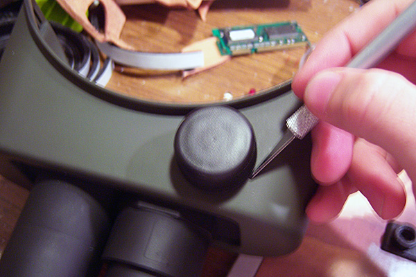
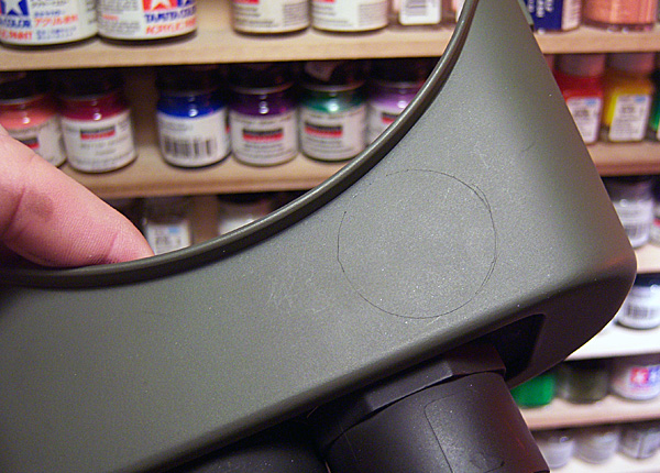
This gives me a ghost outline so I can score the inside diameter with my exacto and dremel so the glue will have a nice rough surface to hold to:
Since the cap I'm attaching has a lot of room, I choose some scrap pieces to use as filler so that I don't have to use 3-4 glue sticks:

First I add some glue to the cap, then start placing filler bits in between glue layers. Finally I make sure the last layer is pure glue then flip it over and press it to the scored area on the frame. In this case, I a little bit of hot glue has escaped:

But given time to firm up, it's easily cut off with trusty exacto knife:

I pick another knob piece for the top, but since its bottom is flat there's no need to outline and score it like the large cap:
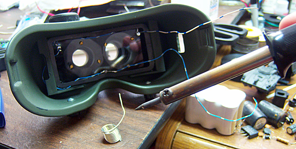
Now it's time to drill holes for each LED:

I solder the LEDs in sequence, a blue LED to each corner and the flashing one to the bottom-middle. They are arranged in series so that with each drawing 3 volts they will distribute the 9 volts from the battery evenly. Each LED is held in place with a drop of superglue:
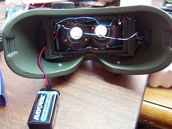
Now I run the wires out of the opening and solder them to the switch which is then snapped into place. Next, the battery snap is ensured plenty of slack and soldered:
For the lenses I add socket head screws as cosmetic tuners:

One on each lense and at different angles to make it visually interesting:
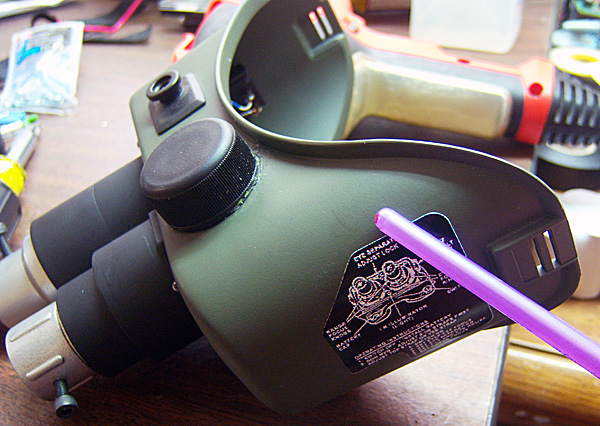
Next up are the vinyl graphics. I take each label and place it carefully then burnish it down with a rounded paint brush handle:
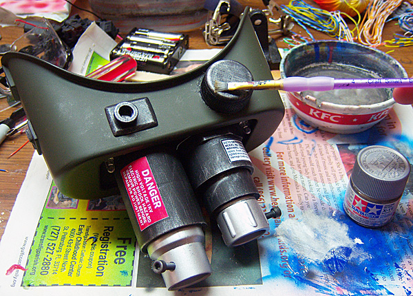
Now I take my favorite paint for drybrushing, Tamiya Chrome Silver, and apply it to the black parts. First I stroke in one direction, then 90 degrees in the other direciton. This gives the lenses and knobs a worn metal look:
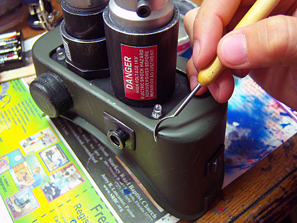
Now I take a curved sculpting tool and create some scratches and nicks. I also gently scrape the edges down to the black base coat. Weathering should be done slowly, as it's very easy to over-do and generally less is more:
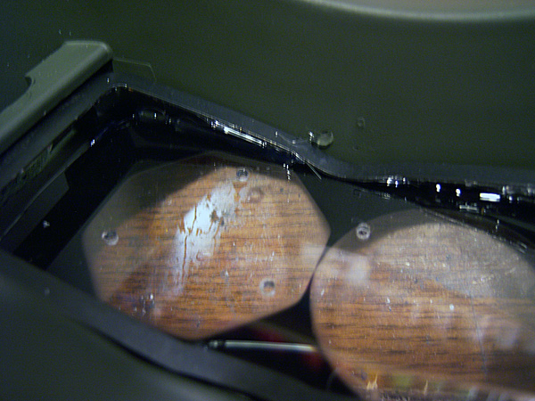
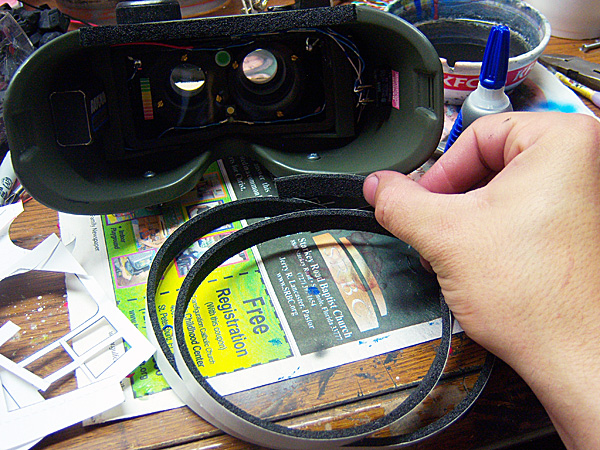
Now I take some labels and apply them to the inside to recreate the HUD look from the movie:

For comfort I add some strips of foam weather striping to the inside rims:
Now I reattach the elastic band and light 'em up!:

|
|